Device Support
XClock supports various data acquisition (DAQ) devices for clock generation. This page provides device-specific information, wiring diagrams, and configuration details.
Supported Devices
LabJack T4
The LabJack T4 is the primary supported device for XClock. It’s a USB-based data acquisition device with excellent timing precision.
Specifications:
Base clock frequency: 80 MHz
Available output channels: 8 flexible I/O (FIO0-7) + 4 extended I/O (EIO0-3)
Trigger input: DIO4
Maximum clock frequency: Limited by divisor calculations
Minimum clock frequency: ~1 Hz
Advantages:
Affordable and widely available
USB-powered, no external power needed
Cross-platform support (Windows, macOS, Linux)
Precise internal clock
Multiple simultaneous outputs
Wiring Diagram
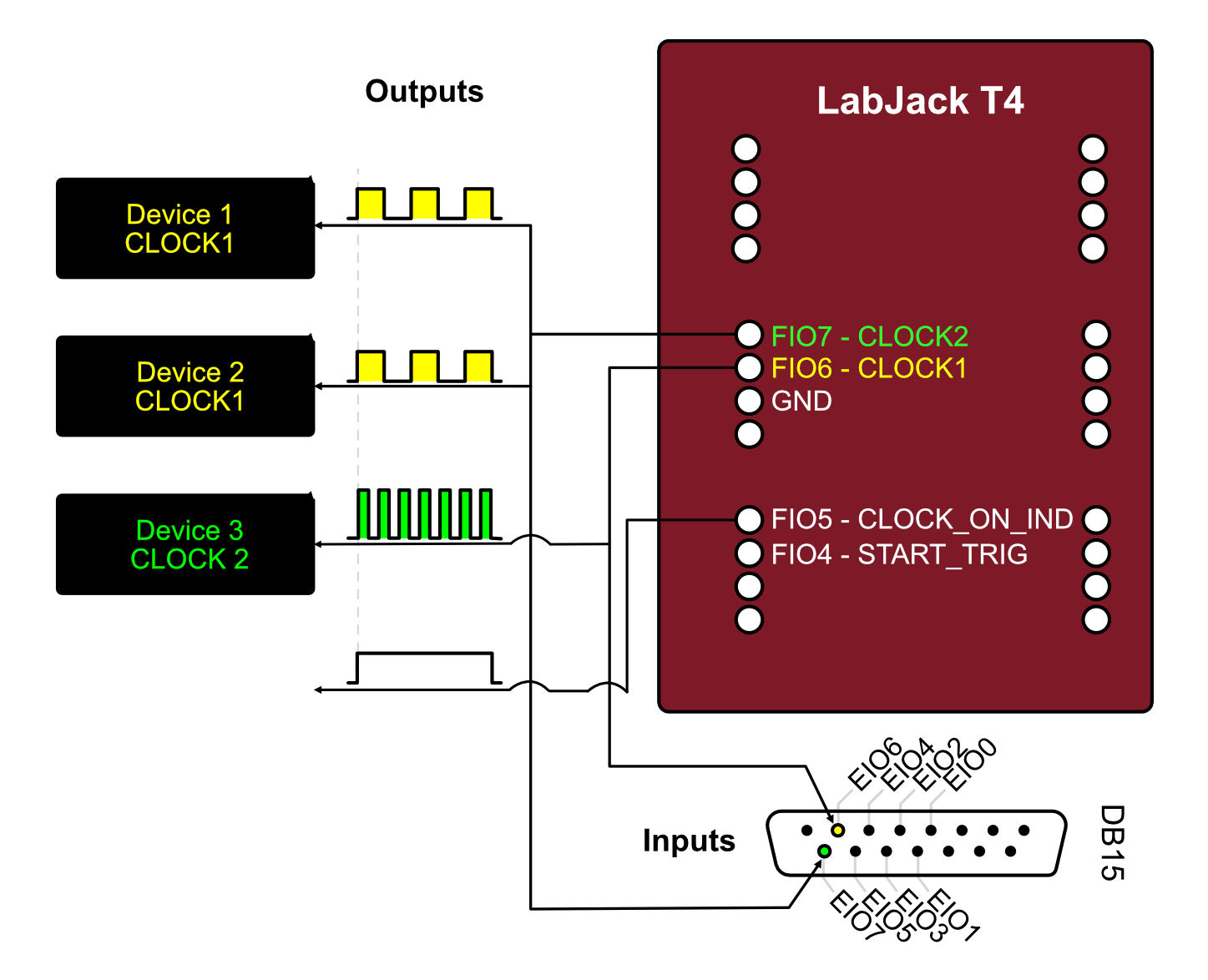
Recommended Wiring:
Clock Outputs: FIO0, FIO1, FIO2, FIO3 (first 4 channels recommended)
Trigger Input: DIO4 (for external trigger start)
Ground: GND (connect to equipment ground)
Power: USB (no additional power needed)
Pin Configuration
Pin Name |
Function |
Type |
Description |
|---|---|---|---|
FIO0-7 |
Clock Output |
Output |
Flexible I/O, can be used for clock signals |
EIO0-3 |
Clock Output |
Output |
Extended I/O, additional clock channels |
DIO4 |
Trigger Input |
Input |
External trigger for synchronized start |
GND |
Ground |
- |
Common ground reference |
VS |
Power Out |
Output |
5V output (USB power) |
Available Channels
Query available channels in Python:
from xclock.devices import LabJackT4

t4 = LabJackT4()
output_channels = t4.get_available_output_clock_channels()
print(f"Clock outputs: {output_channels}")
# Output: ('FIO0', 'FIO1', 'FIO2', 'FIO3', 'EIO0', 'EIO1', 'EIO2', 'EIO3')

trigger_channels = t4.get_available_input_start_trigger_channels()
print(f"Trigger inputs: {trigger_channels}")
# Output: ('DIO4',)
Clock Frequency Limitations
The LabJack T4 uses a divisor-based system for generating clocks from the 80 MHz base clock. Not all frequencies are achievable exactly.
Achievable frequencies:
Frequency = 80,000,000 Hz / (divisor × roll_value)
Divisor: 1, 2, 4, 8, 16, 32, 64, 256
Roll value: 1-65536
XClock automatically calculates the closest achievable frequency:
channel = t4.add_clock_channel(clock_tick_rate_hz=100, ...)
print(f"Requested: 100 Hz")
print(f"Actual: {channel.actual_sample_rate_hz} Hz")
Example: Basic LabJack T4 Usage
from xclock.devices import LabJackT4

# Initialize
t4 = LabJackT4()

# Add two synchronized clocks
t4.add_clock_channel(
    clock_tick_rate_hz=60,
    channel_name="FIO0",
    duration_s=10.0,
)

t4.add_clock_channel(
    clock_tick_rate_hz=100,
    channel_name="FIO1",
    duration_s=10.0,
)

# Start and wait
t4.start_clocks(wait_for_pulsed_clocks_to_finish=True)
t4.close()
Troubleshooting LabJack T4
Device not found:
Install LabJack LJM software
Check USB connection
Test with Kipling software (included with LJM)
Permission errors (Linux):
Set up udev rules for USB access (see Installation)
Unexpected frequencies:
Check
actual_sample_rate_hzto see achieved frequencyTry different target frequencies
Some frequencies may not be exactly achievable
Dummy DAQ Device
A software-only device for testing and development without hardware.
Features:
Simulates all XClock functionality
No hardware required
Same API as real devices
Useful for unit tests and development
Limitations:
No actual output signals
Timestamps are simulated
Cannot trigger external equipment
Example: Using Dummy Device
from xclock.devices import DummyDaqDevice

# Initialize dummy device
dummy = DummyDaqDevice()

# Use exactly like a real device
dummy.add_clock_channel(clock_tick_rate_hz=100, duration_s=5.0)
dummy.start_clocks(wait_for_pulsed_clocks_to_finish=True)
dummy.close()
Use cases:
Testing code without hardware
Development and debugging
Automated testing
Learning XClock API
Device Comparison
Feature |
LabJack T4 |
Dummy Device |
|---|---|---|
Hardware required |
Yes |
No |
Actual outputs |
Yes |
No (simulated) |
Timestamp accuracy |
High (ns) |
Simulated |
Cost |
~$200 |
Free |
Platform support |
All |
All |
Max channels |
12 |
Unlimited |
Trigger input |
Yes |
Simulated |
Connection Examples
Single Camera Synchronization
Connect one camera trigger input to LabJack FIO0:
LabJack T4          Camera
---------          --------
FIO0     ------>   Trigger In
GND      ------>   Ground
Multi-Camera Setup
Connect multiple cameras to different channels:
LabJack T4          Devices
---------          --------
FIO0     ------>   Camera 1 Trigger
FIO1     ------>   Camera 2 Trigger
FIO2     ------>   DAQ System Trigger
GND      ------>   Common Ground
External Trigger Start
Use external signal to start all clocks simultaneously:
Trigger Source     LabJack T4          Cameras
--------------     ----------          -------
Trigger Out ----> DIO4
                   FIO0      ------>   Camera 1
                   FIO1      ------>   Camera 2
                   GND       ------>   Common Ground
Electrical Specifications
LabJack T4 Output
Logic level: 3.3V (TTL compatible)
High level: ~3.3V
Low level: ~0V
Output current: Max 6 mA per pin
Rise/fall time: ~20 ns
Warning
Do not exceed maximum output current. Use buffer circuits if driving high-current loads.
Signal Buffering
For driving long cables or multiple devices, use a buffer:
LabJack FIO0 --> 74HCT244 Buffer --> Camera Triggers (multiple)
Recommended buffer ICs:
74HCT244 (non-inverting)
74HCT541 (non-inverting)
SN74LVC244A (low voltage)
Device-Specific Best Practices
LabJack T4
Do:
Use FIO0-3 first (most reliable for clocks)
Keep cables short (<2m) for best signal integrity
Connect grounds between all devices
Test frequencies with short pulses first
Monitor
actual_sample_rate_hzfor frequency accuracy
Don’t:
Exceed 6 mA output current per pin
Apply voltages >3.6V to any pin
Use extremely long USB cables (>5m)
Hot-plug while clocks are running
General
Do:
Always call
close()when doneUse
withstatements for automatic cleanup (if supported)Check available channels before adding clocks
Validate wiring before starting clocks
Record timestamps for critical synchronization
Don’t:
Add more clocks than available channels
Mix continuous and pulsed clocks without planning
Ignore actual vs. requested frequencies
Share ground connections with noisy equipment
Performance Characteristics
Timing Accuracy
LabJack T4:
Base clock: 80 MHz ± 20 ppm
Jitter: <1 µs
Channel-to-channel skew: <100 ns
Long-term drift: <50 ppm/°C
Timestamp Resolution
When recording timestamps:
Resolution: 1 ns (nanosecond)
Accuracy: Limited by base clock accuracy
Format: 64-bit signed integer
Future Device Support
Planned support for additional devices:
National Instruments DAQ: USB-6001, USB-6008, USB-6343
LabJack T7: Higher precision version of T4
Arduino-based: Low-cost alternative
Raspberry Pi GPIO: Software-timed clocks
Note
See Adding New Device Support for information on adding support for new devices.
See Also
Installation - Installing device drivers
Quick Start Guide - Basic usage examples
Adding New Device Support - Adding new device support
Devices API Reference - Device API reference